The Methods and Nuance of Failure Analysis
The world of reliability testing is full of terms that are both self-explanatory and yet also nuanced. Failure analysis is at the top of that list – as the name suggests, this family of tests involves bringing a product to failure (or near to failure), and then determining the root behind the failure. While this term has expanded to many industries and manufacturing processes, ARL and our partners primarily focus on failure analysis as it applies to microelectronics and PCBs.
Failure analysis is multidisciplinary and can involve an entire battery of tests which all boil down into two categories: destructive and non-destructive. Knowing when and how to design and deploy these different methods can be tricky – many engineers consider failure analysis to be both art and science. When providing failure analysis services, ARL and our partners focus on three main areas of testing methods – visual inspections, x-rays and “dye and pry.”
Visual Inspections
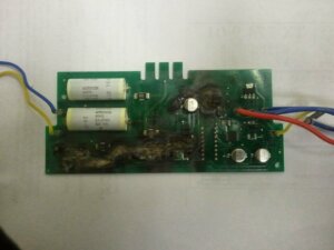
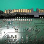
The information gained by first inspecting a product with the human eye forms the basis for all other tests in the process. Visual inspections are done with the unaided eye and with low-level magnification. They are conducted to identify imperfections, such as fractures or burn marks, that can inform further testing. The real expertise at this step is in the lighting and photography techniques involved in documenting the findings and knowing what failure mode could cause various imperfections.
X-Rays
The use of x-rays is another nondestructive test we often perform, and can involve a number of different techniques. As one may expect, x-ray testing can identify cracks, voids, wire sweep and other imperfections that wouldn’t be detectable in a visual inspection. One of the most widely used x-ray techniques for this work is radiography, which creates a 2D or 3D rendering of the test subject. If chemical analysis is needed, another x-ray technique used widely is x-ray fluorescence spectroscopy.
Dye and Pry
Another aptly named technique, dye and pry submerges a PCB into a colored dye to inspect for cracks. The dye is forced into any potential cracks through the use of a vacuum. The dye is then cured using high temperatures in a “bake-out.” Once the dye is set, the PCB is pulled apart and inspected to see if the dye has permeated into the test subject. Although dye and pry is a destructive test method, it produces substantial results. The dye is able to spread throughout the PCB simultaneously testing every solder joint and reveal tiny cracks undetectable by x-ray.
 Next Steps
Once data has been collected through the prescribed tests, a failure mode can be determined along with corrective actions the client can take. Potential sources of failure can happen at any stage of the manufacturing process – sourcing, assembly, packaging or shipping – so it’s vital that the results of the tests are interpreted through the lens of each of these stages.
If you’d like to know more about failure analysis or other services ARL and our partners provide, contact us today.